
Now for the final stretch.
For those who missed it, Part 1 is here. Part 2 is here. Make sur you read them both before continuing.
First, your magazine release assembly. These are the parts you’ll need
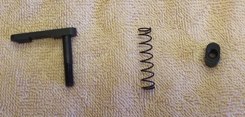
Insert the magazine catch through the left side of the receiver and the spring and button through the right side over the threaded shaft. While pushing the catch in as far as it will go, turn and thread the button. When you can turn it no more without scratching the receiver, line the button up with the hole in the receiver and push it in as far as it will go. This will cause the catch to be pushed out the side of the receiver so that you can further thread it into the button. Stop before the catch makes contact with the receiver, line it up with the catch slot and release the button.
Next, the bolt stop assembly. These are the parts you’ll need
![]()
You’ll need to have a 3/32 punch to align the parts through the pin hole. Insert the spring into the hole, and the small end of the detent into the spring. Set the bolt stop into the notch. Align the hole of the bolt stop with the hole son either side of the housing and push your punch through from the rear hole. From the front hole, align the roll pin and tap gently with your brass punch, and if needed, your tapping hammer until flush on both sides of the housing.
This is where you want to make sure you’ve taped off you receiver on both side of the housing and the full length of the receiver.
And now, two assemblies in one! The grip assembly and the safety assembly. Here are the parts you will need
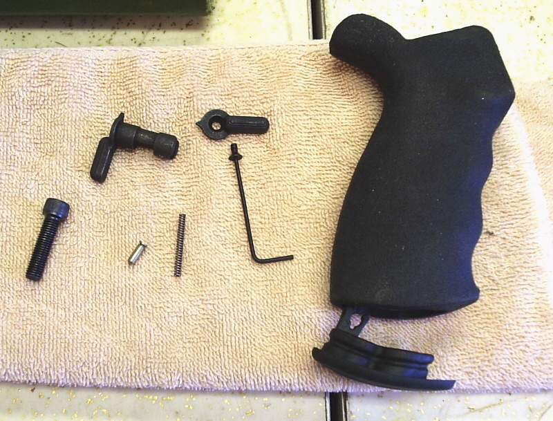
It is easiest to do this with the receiver either vertical or upside down. I prefer to do it upside down so as to let gravity do my work for me, but adjust your vise block appropriate to your preference and on we go.
Insert your safety from the left side of the receiver and rotate it to the SAFE position. Drop in the detent, pointed end down. Follow with the detent spring. Next, attach your grip. Note that there is a hole in the top of the grip for the detent spring. Do not crush your detent spring. Once you have the grip flush with the receiver insert your grip screw and tighten with the Allen wrench. There are no real torque specs, but hand tight will do. If you have an ambi-safety such as the one shown, now would be a good time to secure the right side of the safety lever.
Also, return the receiver to the right-side up position.
Next up, the front and rear connection pins. These are the parts you’ll need for the rear pins. They are the same for the front, minus the stock plate on the left. The front pin is the longer of the two with the cut-out on the head.
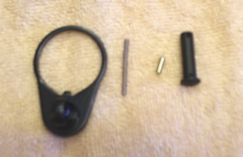
For the front pin, using the handy-dandy tool shown in Part 1, insert the detent spring and then the detent through the hole of the tool and into the hole in the receiver. Using you 1/16 punch, compress the detent and spring into the receiver, just far enough that you can rotate the tool. Holding the handy-dandy tool firmly, remove the punch and grab the front pin. Align the left end of the front pin with the right end of the tool, with the cut-out on the head facing towards the rear of the receiver, push the handy-dandy tool to the left, which should self-insert the detent into the front pin.
There are two sets of instructions for the rear pin: One for a fixed stock and one for a collapsible stock. Since most folks do fixed stocks their first time, I will explain those and put any notes for collapsible stocks in parentheses and italics.
You will be threading your stock tube onto the receiver. You will need the sock tube tool and these parts (you will also need to make sure that your stock tube attachment plate and locking nut are attached to the front of your stock tube).
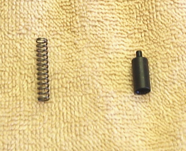
You will see a hole in the receiver in the bottom of the threads. Once you get the tube partially threaded you will want to insert the stock tube detent spring and the stock tube detent and hold them down with your 3/32 punch tip.
You have hopefully also noticed a notch cut in the threads of your stock tube. Using your stock tube wrench, tighten the tube until this notch surrounds the tip of the stock detent then release the punch from the detent.
Insert the rear pin from the right hand side. (At this time you can insert your last detent and its spring into the rear hole and push forward your stock plate. Hold it there and tighten your tube nut with your stock tool).
Insert the detent and then the spring. Take caution not to bend the spring and slide your stock over the tube.
Put your stock butt plate on the rear of the stock and thread in the longer of the two butt plate screws into the upper hole. Tighten that screw down and then thread and tighten the short screw into the bottom hole.
Insert your buffer recoil spring. You’ll notice three notches in the head of the buffer. Insert the buffer, making sure that one of these notches goes over the detent. Twist the buffer so that one of the round sides is blocked by the detent.
You are done. Time for your function checks.
Trigger/hammer. Then safety/trigger/hammer. Magazine release. Bolt stop. Both attachment pins.
If you have an upper, attach it. and enjoy.
It’s a little bit different when you have to fit a “bullet button” mag thing – but after the first lower the second one went without a hitch! 🙂